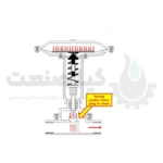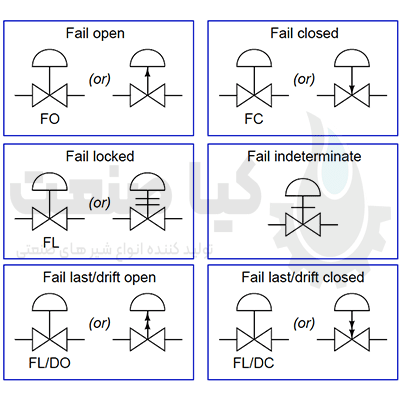
The failure mode of the control valve is indicated on the instrument diagrams by an arrow (assuming that the valve body closes directly where the movement of the stem towards the body and the movement of the stem away from the body causes the valve cut to open) or abbreviations such as “FC” ” (Failed Closed) and “FO” (Failed to Open) are displayed.
Other failure modes are also represented by a set of other symbols that we will examine below.
Failure mode of the control valve
In order for a pneumatic or hydraulic valve to fail in the locked position, an external device must trap fluid pressure in the actuator diaphragm or piston housing in the event of loss of supply pressure.
Control valves that fail in place and move in a specific direction are usually actuated by double acting pneumatic piston actuators.
These actuators do not use a spring to provide a definite failure mode, but instead use air pressure to both open and close the valve.
If air pressure is lost, the actuator cannot open or close the valve and therefore tends to remain in position.
If the valve stem is unbalanced with trim, the forces applied to the valve plug will move it in one direction (causing thrust).
It is important to note how the failure mode of a valve is often related to its control function (air to open, air to close). That is, an open air pneumatic control valve closes when air pressure is lost, and vice versa
This is an important fact because good safety engineering requires that process risk factors determine the correct failure mode of the valve rather than controlling contract or system habit.
It is easier for people to understand the operation of an air-to-open control valve than an air-to-close valve (more signal = more process fluid flow), but this should not be a guiding principle in valve selection.
The air control valves of the pneumatic valves close normally.
This means that they are only suitable for a specific process control application.
This process is safer to fail with the valve closed than with the valves open.
If the process is safer with a broken-open valve, the control valve pneumatically specified for that application should be air-tight.
First, determine the safest failure mode of the control valve.
Then select or configure the instrument actions so that the most likely failure modes of the signal path result in the control valve continuously moving to the safest position.
For example, consider this automatic cooling system for a large power-generating engine:
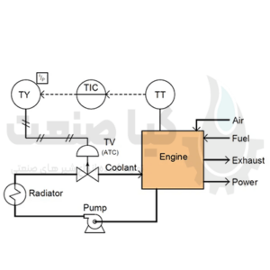
Obviously, closing the valve is more dangerous for the engine than not opening the valve. If the valve is not closed, the engine will surely overheat due to lack of cooling.
If it is not opened, the motor will simply run cooler than designed and the only negative consequence is reduced efficiency.
With this in mind, the only reasonable choice for a control valve is one that does not open (air to closed).
However, our choices in tool action don’t end at the control valve.
How should the temperature transmitter, controller and I/P converter be configured to work?
In either case, the answer should be to act so that the valve defaults to its safe (fully open) position in the most likely error of the input signal.
Stepping through the control system from the valve to the temperature sensor, the next device we encounter is the I/P converter. Of course, its job is to convert the 4-20 mA current signal into pneumatic pressure that the valve actuator can use.
Since we know that the failure mode of the valve is based on loss of active air pressure, we want the I/P to be configured to produce the minimum pressure in the event of an electrical fault on the 20-4mA input. Signal wiring
Whether the wiring is shorted or not, the result will be 0mA at the I/P input terminals.
Therefore, the configuration of the I/P converter should be straightforward, such that an input signal of 4 to 20 mA produces an output pressure of 3 to 15 PSI (ie, minimum input current produces minimum output pressure).
The next tool in the loop is the controller. Here, we want the most likely failure of the input signal to result in the minimum output signal, so the valve (once again) defaults to the “fail-safe” position.
As a result, we need to configure the controller for direct operation, just like an I/P converter (ie, a reduction in the PV signal from a broken wire or loose connection in the input circuit results in a reduction in the output signal).
Finally, we come to the last tool in the control loop:
Temperature transmitter (TT). As with most tools, we have the option to configure it for direct or reverse operation.
Should we choose direct (ie hotter motor = more mA output) or reverse (hotter motor = less mA output)?
Here, our choice should be such that the overall effect of the control system is negative feedback. In other words, we need to configure the sender so that a hotter engine leads to an increase in coolant flow (opener control valve).
Since we know the rest of the system is designed so that a minimal signal anywhere tends to drive the control valve into its fail-safe position (wide open), we must choose a reverse-acting transmitter, so the engine will run hotter. It leads to a decrease in milliamps. (signal from transmitter)
If the transmitter has a sensor “burn” mode switch, we must place this switch in the low-scale burnout position, so a burned-out sensor will result in a 4mA output (downscale 4-20mA). It directs the valve to the safest position (in the open position).
Such a configuration with a closed volupneumatic (air) control valve and a reverse-acting transmitter may seem strange and incomprehensible, but it is the safest design for this engine cooling system.
First, we selected the safest failure mode of the control valve, then we selected the instrument actions such that the most likely failures of the signal path at any point in the system would result in the same valve response.
Of course, it goes without saying that detailed documentation in the form of a loop diagram with the actions of the tool clearly shown is an absolutely necessary part of the whole system.
If the safety of a control system depends on the use of any “non-standard” instrument configuration, it is best to document these settings so that those maintaining the system in the future know what to expect.
Another important detail in this system is to configure the controller so that the operator display for the output signal is still registered in a visual way: 0% should still indicate a closed control valve, while 100% should still indicate a Open the valve.
In the condition that the pneumatic valve is closed (signal to closed from the controller’s point of view), this means that the controller must be configured to show the reverse on the output display, so that the output shows 4 mA (valve open). 100% open and the 20mA output (fully closed valve) indicates 0%.
As confusing as this may be to the technician who must service the controller, it is more important that the operator who uses the controller see something that makes sense every day.
In the event of an emergency, “minor” details like this become critical, and the operator must make decisions in seconds based on the cues he sees.