This article discusses precautions for condensate drain lines installed in main steam lines and condensate drain lines installed in equipment.

Main steam lines
In the steam network, part of the steam loses its latent heat by heat radiation and condenses.
To remove these condensates, several condensate discharge lines (branch line) are often installed at intervals of 30 meters to 50 meters.
However, unlike the device examples described below.
It is difficult to remove all the condensate because the high-velocity condensate drawn by the moving high-velocity steam must collect in the middle.
Most of the condensate in the main steam line is in very small amounts, so a small diameter condensate discharge line is used.
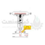
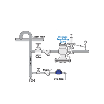
For this reason, it is recommended to install a condensate collection chamber where the condensate drain line is connected to the main steam pipe.
As shown in Figure 4.1, it is installed as a means of increasing absorption efficiency.
If the diameter of the main steam line is up to 100 mm, the diameter of the collecting envelope should be the same as the main steam line.
On the other hand, if the diameter of the main steam line is 100 mm or more, the diameter of the collection bag should be at least half the diameter of the main steam line.
Additionally, since the bottom of the pocket collects dust, the condensate outlet should be slightly higher than the bottom of the pocket.
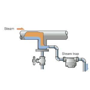
Using the trapping system to install a steam trap
Trapping refers to a trapping system where a steam trap is installed in each condensate discharge path, as shown in Figure 4.2.
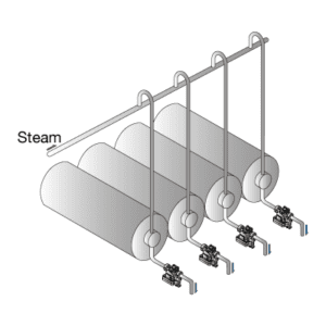
In contrast to trapping, when several steam trap units are connected in the discharge paths and installed in the common condensate discharge line, it is called group trapping. (Figure 4.3)
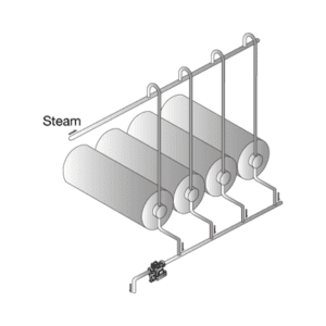
Figure 4.4 shows an incorrect configuration where a steam trap is used to cover the condensate discharge of two devices used at different pressures.
Since the pressure of equipment B is higher than that of equipment A, the produced condensate flows into the steam trap without problems.
On the other hand, the high pressure of equipment B prevents the check valve on the A side from opening and prevents condensate from draining from equipment A.
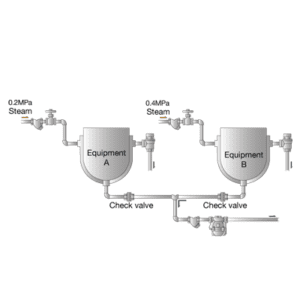
Figure 4.5 shows the case where equipment with the same pressure is used together.
It is assumed that equipment B is under normal operation and the inside of the equipment reaches a predefined temperature.
If equipment A is started in these conditions, it will produce much more condensate than equipment B because it is cooler inside.
As the steam condenses further, the pressure drops, causing steam to flow in from equipment B.
Equipment A must withstand steam and drain condensate.
Therefore, group trapping can prevent the smooth discharge of condensate and negatively affect the performance of the equipment.
This configuration requires fewer steam traps, but this is due to the lack of awareness of the steam trap.
It is important to have a new understanding of the validity of individual trapping.
Steam trap installation position
It is generally recommended that when installing a steam trap, in the condensate drain, this should be done as close to the equipment as possible.
The further the steam trap is from the equipment, the more likely steam is locked between the steam trap and the equipment.
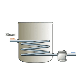
The steam trap should also be installed at the lowest condensate generating position of the device, for example, at or below the lowest point of the heat transfer line in the heat transfer device. (See Figure 4.6)
If you need to install the steam trap in a higher position according to Figure 4.7, pay attention to the following points.
Lifting fittings are installed to install the seal.
Use a line smaller than the vertical line.
The reason for using a water seal in a steam trap is for the following reasons:
When the steam trap has finished draining the condensate, steam flows in and closes the valve, but at this time the startup line is filled with steam.
Finally, condensate is produced again.
But if a seal forms, when steam condenses in the launch pipe and the pressure in the pipe drops.
The condensate immediately enters the pipe and is quickly discharged through the steam trap.
On the other hand, in the absence of a seal, when steam condenses in the start-up line, the pressure drops.
New steam enters the startup line before condensation.
The amount of condensate increases and condensate discharge waits for steam to condense in the pipe.
In this way, there is always a temporary steam lock when the steam trap is opened in the line, but if there is a seal, it will be unlocked in a short time.
If the diameter of the riser line can be further reduced, the unlocking time will be further shortened.
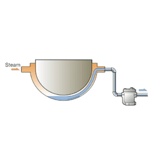
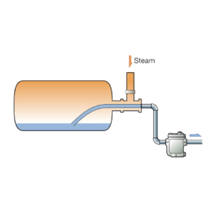 Figure 4.8 Cylinder dryer
The example below is an example of equipment in which the steam trap is installed in a higher position than the gas condensate generator.
In both cases, one end of the siphon tube is immersed in the condensate generator and the condensate is directed through trunnions to the steam trap.
Kiasanat is a supplier of all types of steam traps, thermodynamic steam traps, thermostatic steam traps, thermostatic floater steam traps, Yarway steam traps, Armstrong steam traps, TLV steam traps, Isfahan steam traps, Gestra steam traps, Yoshitaki steam traps, Spirax Sarco steam traps. for you.